Friday, December 27, 2019

Iron Deadpool

Ironman + Deadpool


I have wanted to build a suit of Ironman armor for a long time now, and this year I decided to bite the bullet and get it done. As I was looking through the copious variations shown in the live action movies, I stumbled on a picture of an action figure that someone had painted to match Deadpool and I was just floored by how cool it looked. I decided to give it a shot, and combined parts from a few different editions of Ironman in an attempt to pull off a decent Deadpool variant.


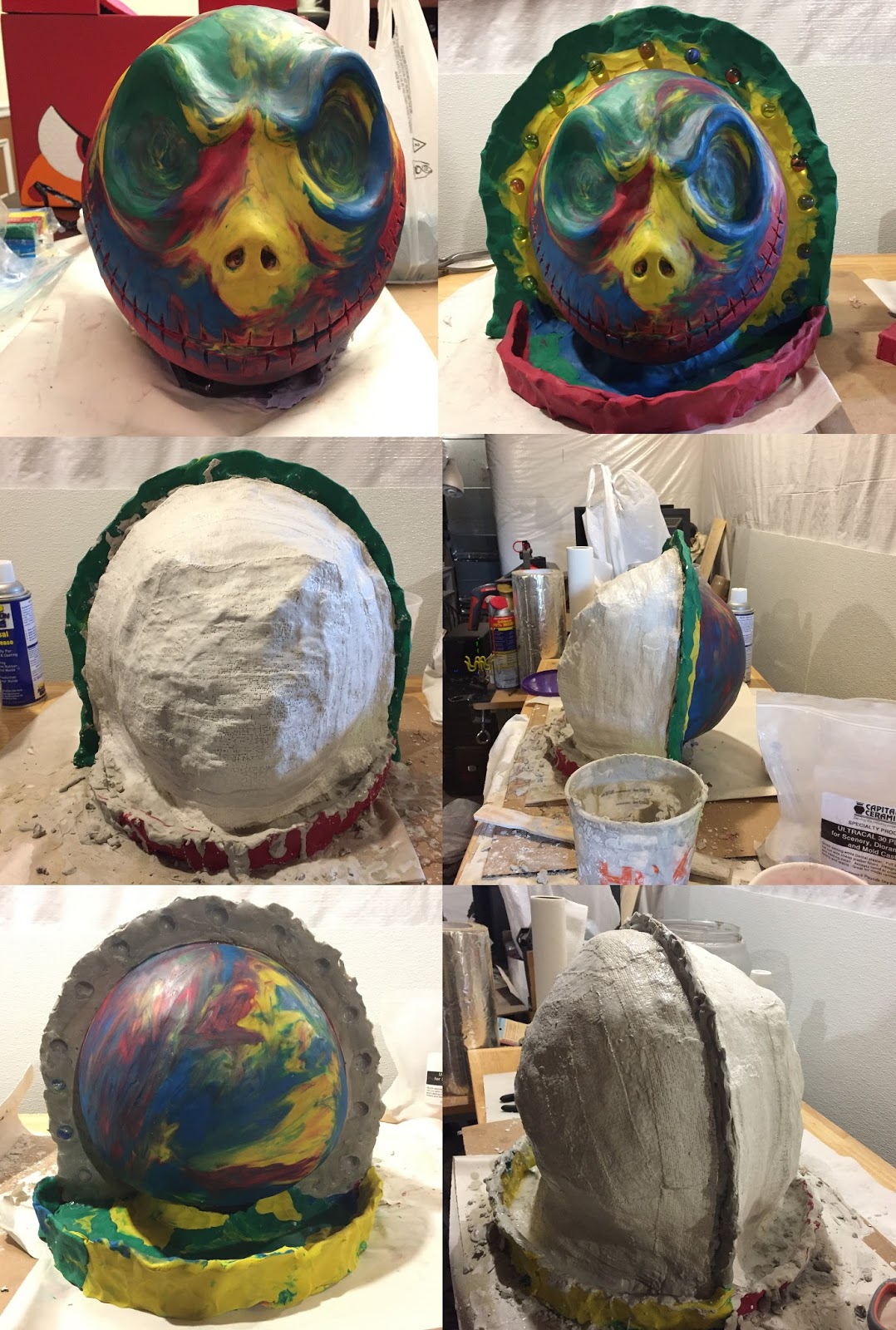
I started with the helmet and thought that the grooves on the MK42 would work well with the eye patterns on the Deadpool mask. I made those patterns more angular than the traditional Deadpool mask to try and fit better with the lines of the helmet. I used my new Anycubic Photon to 3D print the helmet, and used the model provided by Jace1969 on thingiverse.com (thanks to Jace1969 for making such a greta model!). The pieces were too big for the print bed on my Anycubic, so I had to cut down the models into much smaller pieces that I epoxied together after the fact. The Anycubic has been a fairly recent purchase for me, and is a resin based SLA/LCD based printer. The results have been SO MUCH smoother than my FDM fifth generation Makerbot, but the print bed is much smaller. 


I used super glue for the initial bonds, then reinforced with JB Weld for strength, and used spackle to smooth out the lines before painting. It is a bit of a process, but worth it for the results in my opinion. Same story for the rest of the helmet.


I used pieces of clear acrylic with small dots laser engraved onto the surface for the glowing eyes. There was one led glued to the side of each one, and when lit the engraved dots reflected the light made the surface glow fairly uniformly. When off I could see through it perfectly, and as long the lighting outside was fairly bright I could see decently when they were on (though in my basement I was functionally blind when they were turned on). I used a heat gun to soften the acrylic enough to bend into a curve to fit the eye sockets.


The chest and back are also from the MK42 edition of the armor, but I used my FDM fifth gen Makerbot to print these given the size. Even with the larger printer, I think those pieces ended up being around 18 individual prints, each of which took most of a day to print. Once all the pieces were printed, I used melted PLA (the same material they were made from) to seal the pieces together. This forms a pretty solid bond since it melts into the existing pieces and hardens as though it is all single unit. The seams are still quite a bit thinner than the main pieces though, so I reinforced it with fiberglass.

The FDM printer can handle a much larger build volume, but the print surface is much rougher so there is a lot more work to be done to smooth the surface. This is done using many layers of spackle and filler primer with lots of sanding between each application. Once I gave up on making the chest any smoother, I painted and weathered it. I placed strong magnets inside the piece to hold the chest repulsor in place and put together a set of LEDs controlled by a push button to nestle inside the cavity. I then laser cut some acrylic to make the the Deadpool symbol for the front piece. Pressing the center of the Deadpool symbol turns the lights on and off (the light is much more diffuse in person than on camera).


The shoulders and arms were also printed on the Makerbot, and were smoothed, painted, and weathered the same way. I used nylon straps with plastic snap buckles to attach these pieces to one another. I bought an inexpensive jacket and glued straps to the fabric to hold the shoulders and arms in place.


The hands were printed on the FDM printer as well, but only because I made them before I got the resin printer. they would have been much better suited to a resin print. The back plate was attached using elastic straps and velcro, and the finger joints were each glued to the finger of a black painted nitrile glove. 


The hand repulsors are a circular board with bright LEDs. The magnet switch activated controller that manages the LED brightness and sound effects are part of a kit that I picked up. I laser cut a clear acrylic disk to cover the LEDs and diffuse the light, and sewed that into a long cloth glove that I wore under the 3D printed pieces.


Below is a video of the sound and lighting effects of the hand repulsor from the kit I purchased.


The remainder of the suit was made using EVA foam using a pepakura template. This was mainly driven by the fact that it was already October by this point and I needed to have the costume ready for Halloween (note to self: add a link to the pepakura files). Normally pepakura templates are printed on paper, cut with an Xacto knife, glued together, and then coated in fiberglass to harden them. Foam templates are similar, but generally less complex because the edges of the foam can be glued together directly, whereas the paper variant requires lots of little tabs and inserts to act as a gluing surface. 

Working with foam instead of paper can sometimes be tough because cutting clean edges out of foam is difficult. The laser cutter has made this WORLDS easier as it cuts clean edges every time and removes the most tedious step of working with pepakura.


To make the boots I started with an old pair of shoes and a set of heavy duty shop LEDs to act as the foot repulsors. I cut holes in the bottom of the shoes and ran velcro straps through shop lights and shoes to attach them so that they can be easily removed to change out the batteries. I then used more foam pepakura templates to make a shell around the shoes.


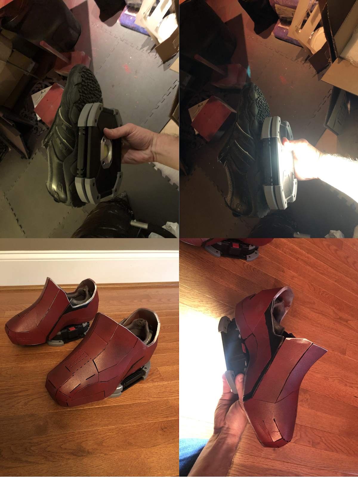
The foot repulsor LEDs show up pretty well indoors, but are less noticeable out in the sunlight.


Here is a quick video moving around in it and activating the hand repulsors:


It was a ton of work to complete the costume, but there is no way I could have done it without the help of my wife doing the lion's share of watching the kids for the month and a half that I spent in the basement working on it. Not to mention her begrudgingly but diligently helping me in and out of it at the company party.


Saturday, November 3, 2018

DIY Gaming Table - WIP


Around November of 2017 I started building a custom gaming table for playing RPGs like Pathfinder and Dungeons & Dragons. I was inspired by the Geek Chic tables that used to be available, but those were way too expensive for my budget. By early January the table was "complete enough" that we could start playing on it. That, combined with the fact that my new Glowforge laser cutter had arrived, was enough distraction that I pretty much stopped working on it. I am trying to motivate myself to finish it now and am hoping that posting about it here will help push me to work on it (plus my Glowforge caught on fire and destroyed itself, so that is no longer a distraction).

The table has a 55" TV embedded in the center for displaying maps in the game. I use roll20.net most of the time to display the maps with "Game Master" display running in a browser on my second monitor and the "Player" display running in a different browser on the TV screen (both displays are plugged into my laptop). The table also has hinged Geek Chic inspired cubby/tables for laptop/tablet/character sheets, etc., and additional slide out tables that we use to eat from when we play. I also built embedded dice towers for the corners that you will see in some later pictures.


I used TinkerCAD to create a 3D design of the table, and stayed pretty close to the original design with the build (you will see a few differences between the design and the actual build). The design are available here on the TinkerCAD website: Gaming Table Design. The units are displayed in millimeters in TinkerCAD, but they represent inches for the build itself. The entire table is about 5 feet by 7 feet, so it is fairly large.


I built the frame using 2x6 boards (I think the CAD design shows 2x4s for this, but I decided to go larger for a little added strength). I cut 1.5 inch grooves in each piece, leaving 4 inches of board beyond each groove. this allowed me to slide the boards into one another to provide a frame. I then added 1x6 boards across the top to create the table surface which rings around the TV screen.


I then made an inner frame using 1x3s to sit inside the outer frame and snugly hold the TV in place. The crescent shaped grooves in the inner frame were added to so that the TV could sit on a swivel mount and be lifted into an upright position in case we wanted to watch something on the TV rather than playing on top of it.


The legs were each made from three 2x4s glued and screwed together with the center board 5.5 inches shorter than the two outer boards. The legs were then slid onto the outside of the longer frame boards and bolted in place as shown in the picture above.


Unfortunately I didn't take very good pictures of the mount set up when I was building it, but I used angle iron to bolt a plank to the sides of the frame and attached the swivel mount to that plank. The temporary boards in the top right picture holding the TV in place were replaced with a rail that allows the TV to slide back and forth as it is shifted into an upright position.


I wrapped the outside of the frame using 1x10 boards and then attached 1x6 boards to the bottom to act as the lower shelf of the cubbies for each player. I then added an end cap to each corner for additional support.


I bolted some more angle iron together to make a track for the slide out shelves which were each made out of a 1x12 plank (maybe 1x10, I do not recall for certain). There is a hole cut in the end of each slide out shelve to make it easier to pull them in and out. I am planning to add cup holders to the ends of these, but have not done it yet.


I used narrow flip top hinges with angled cuts of 1x6 boards to make the hinges and added strips of craft foam to soften the impact if my kids slam them shut. The hinges were purchased from the Lee Valley website here. The image below shows the hinge pieces in a closer view.


I installed power outlets in each corner which provide a total of eight power plugs and eight USB ports to the table.


Below are some pictures of the TV lifted into the upright position. I used my Glowforge laser cutter to make the custom the dice tower and dice shelf that you can see on the corner.


The dice tower folds up so that it can side into the box mounted on the corner. There are magnets embedded in the base of the tower that it can be placed on top of the container as shown in the video below.


I still have some work to do to finish up the table and then I will stain it. It has definitely made playing a lot more convenient over the last year, and has been a fun project to work on. I mentioned above that I use often use roll20.net to set up and display maps for our games, but lately I have been creating some 3D maps using SketchUp and Table Top Simulator. The pictures below are screenshots from some maps I created for the Pathfinder Giantslayer and Ruins of Azlant campaigns (using the 2D maps from the publisher as a starting point).


The 3D maps are a lot more work to set up, but can make visualization easier for the players as well as adding a lot of depth to the game in my opinion.


Monday, October 31, 2016

This is Halloween!

Jack Skellington from The Nightmare before Christmas!


This Halloween I decided to try for a character that has been a Halloween favorite of mine since I was a little kid - Jack Skellington from The Nightmare before Christmas. This costume meant a lot to me because my mother passed away this year and Halloween was always a huge production in our family. She always handmade my costumes when I was a child and transformed the house inside and out with Halloween decorations. When I was older we always geeked out together about the costumes we were working on. Even throughout this last year in the hospital, we were talking through the costume she was going to wear once she got better (I was making the armor and she was sewing the clothing). Not being able to talk through this one with her as I built it made the process a bit sad, but I think she really would have liked it. This one is for you mom.


I started by modifying a 3D model of a skeletal hand. In the movie Jack has pretty simple, three fingered hands, but I thought it would be cool to do a more realistic version. The 3D model that I used a basis was obtained from thingiverse.com here: Skeleton Hands. Using Blender, I first split up the model along each joint, then created a groove within each one with a larger cylinder at the innermost edge. I also created a model of a piece which would fit perfectly inside the space created by those grooves. This is what I would 3D print and use to create the silicone "joint" pieces that would assist movement of the fingers. Finally, I added a small hollow cylinder to the mid-point of each finger bone. This created a channel that I could run a string (30 pound fishing line) through to pull each finger into a curling motion.


I put small metal hinges on the inside of each finger joint so that they would bend like a normal finger motion. A string was tied into the cylindrical holes so that the fingers could be pulled into the curled position. Once that was in place, I created a mold of the "joint" piece using Apoxie Sculpt and poured silicone into it. Once it cured, I was able to push it into the grooves at the finger joints and it provided the stretching mechanism that pulled the fingers straight again once pressure on the strings was released. Initially the fingers would bend at each joint much farther than a natural joint due to the hinge placement. I used a bit of Apoxie Sculpt at each hinge point to create a barrier which stopped the curling motion at a fairly natural point. After quite a bit of trial and error printing a few pieces, testing the movement, adjusting the model, printing again, rinse, repeat, I got to a point where I was pretty happy with the fingers and printed an entire hand.


Once the hand was printed and assembled, I made a frame that would attach to the base of it to hold my actual hand. I would slip my hand through the black circle at the bottom of the frame, and my thumb would rest upon/wrap around the cylinder in the center. The frame ended up being a little too wide initially (it made my arm look fat and flat), so I took it apart and trimmed it down to be narrower. I didn't get a very good picture of this after the fact.


Once it was all assembled, I sewed the strings from each finger into a glove that rested inside the frame, then painted the hand white, and attached a sleeve over the frame to extend the one in the jacket I would be wearing.


Now that the hands were completed, I moved on to the mask. This process was very similar to the one I used to make the Groot mask linked here: I am Groot!. For this mask I used some different materials though. The Groot mask was made using a silicone mold, which captures details really well, but was an epic pain when casting the mask and got destroyed in the process. For the Jack mask, I used Ultra-Cal 30 instead (essentially a mixture of plaster and cement). This created a very rigid mold, which held together well and  was easy to cast with, but didn't capture details quite as well. The Groot mask itself was made out of Poly Foam, which sets really quickly and expands to fill the space between the mold and the life cast, but which did not hold paint very well - cracking and flaking eventually from the mask. The Jack mask was made out of latex, which doesn't expand (shrinks actually), and took a bit longer to cast. That said, by mixing acrylic paint with additional liquid latex, I was able to make a paint which stuck really well to the mask.


To make the mask, I used a cement life cast of my head as a base and sculpted the shape using an oil based clay. Once the sculpt was done, I used more clay to create a barrier around the front half of the sculpt. This barrier allowed me to cover the front half of the sculpt in Ultra-Cal without touching the back half. This is important for making a two part mold. I stuck marbles in the clay to create registration keys so that the two halves of the mold would fit together correctly when I poured latex into it later. Once the front half cured, I peeled away the clay and covered the edges of the cured Ultra-Cal with vaseline so that the two halves of the mold wouldn't stick together once the back half cured. I then covered the back with Ultra-Cal as well.


Once the mold was fully cured, I pulled the two halves apart and cleaned out the clay that had stuck to the Ultra-Cal. There were a few holes in the mold in which it didn't press tightly enough against the clay before hardening (a thinner solution of the Ultra-Cal produces better details, so that should be your first coat - mine was not thin enough in a few places). Luckily these spots were mostly on the bottom back of the mask. I decided to patch these with Apoxie Sculpt rather than using more Ultra-Cal to smooth it out. This was a mistake! The latex didn't cure as well against the Apoxie Sculpt, so it left some holes in the mask in those spots. Use Ultra-Cal to patch Ultra-Cal! I duct taped the two halves of the mold together, then sprayed the inside with mold release, and placed the mold upside down in a padded box. Once the mold was stable, I filled the entire thing with RD 407 Liquid Mask Latex. I let the latex sit inside the mold for an hour, and then poured the majority of it back into the bucket it came in. The longer you leave the latex sitting inside the mold, the thicker your mask will end up being because the latex that is touching the Ultra-Cal will cure over this period, but the remainder inside will remain liquid and can be re-used later. An hour resulted in a pretty thick mask, but if I did it again I would probably leave it a little longer simply because this mask doesn't really need to flex of bend at all while I am wearing it and thicker = sturdier.


Once the latex cured (I gave it about 24 hours), I carefully peeled it out of the mold, pouring talcum powder into it as I removed it. At this point, the latex still has some curing to do, but you want to pull it out because the latex shrinks as it cures (about 20%), so it can deform if it is left in the mold for too long. You should take this shrinkage into account when sculpting so that it will still fit on your head once it shrinks. The latex will stick to itself if you don't cover it in the talcum powder, and this could ruin your mask. Once it was out of the mold, I trimmed off the rough edges from the seals in the mold, and cleaned off most of the talcum powder. The back had the holes in it that I mentioned before, so I covered the inside with painters tape and then painted on layers of latex to fill in the gaps. After trying it on for size (and taking a terrible selfie since I could not see), I cut the eye and nose holes, and painted the mask using a 50/50 mixture of latex and acrylic paint.


Now that the mask was completed, I needed to make the rest of the costume. In order to accentuate Jack's long lanky frame (and fit the elongated arms), I used the same drywall stilts that I wore for the Groot costume. To make the jacket, I frankensteined two thrift store suit jackets. I cut and sewed the primary jacket short in the front, and made coat tails for the back, lining them with thick gauge wire so they would stay in a curled position. The bow tie was made from Apoxie Sculpt and craft foam. The pin stripes I hand painted on the night before the company costume contest (of a late night... procrastination is not your friend).


To make the pants I sewed four pairs of thrift store dress pants together in order to get the right length and width. In retrospect, it would have been much easier to just sew black material over a single pair of dress pants, but hind sight is 20/20. The company Halloween party with the wife was a lot of fun, and trick or treating with the kids tonight was a blast (my son was Jack this year as well - he loves the movie even more than I do).


Happy Halloween!


Monday, May 9, 2016

Dragon Door Knocker - 3D Print


I finished up a quick project the other day, and thought I would share. I made this dragon door knocker for my mother. It was 3D printed based on the files located on thingiverse here. The author of the files included a link for finishing techniques on instructables here. I started out following the instructions linked, but ran into an issue that I will describe farther down.


Immediately after printing there was a lot of support material that needed to be scraped off in order to finish the print (the support material is added automatically by the software I use with the 3D printer, it allows the printer to make the overhanging pieces which would otherwise simply collapse). I scraped and sanded off as much as I could see and then put a coat of primer on the piece. It is hard to see fine details before painting the natural PLA because it is translucent. Once I had a coat of primer applied, I scraped off the remaining support material, and used a dremel to smooth it out. It is a bit hard to tell in the picture above, but there was still a lot of material to clean up.


The instructable then recommends using XTC-3D to smooth out the print and make it stronger. This worked really well, and I will probably use it in the future. There was some loss of detail due to the coating, but the smoothing effect was very successful.


The instrcuctable also recommended applying iron powder to the print, and then using ammonium chloride to oxidize it, which would give it a neat aged effect. Unfortunately, I bought the wrong kind of iron dust, which did not oxidize at all. Bummer. So I painted it instead.

The XTC-3D mixed with iron powder dried to a matte black color (the color of the powder), which I painted over in Rustoleum "Flat Soft Iron".


I then sprayed Rustoleum "Metallic Rust" onto a paper towel, rubbed it lightly over the high points, leaving the "Flat Soft Iron" to show through in the crevices.


Finally, I dry brushed gold over the highest points on the piece to provide stronger contrast overall and make the scales pop a little better. One really neat thing about this print is that the support material was set up so that it would hold up the knocker while printing, but once it was removed, the piece would move freely overall. This allowed knocker to have moving pieces, but print out as a single solid unit.